
CorTec’s Innovative Brain Interchange System for Stroke Rehabilitation
Recently the online journal “Open Access Government” published an article about our innovative Brain Interchange System. A forthcoming early feasibility study, scheduled for 2024 in the United States, will investigate its effectiveness. The details of the technology and the system are unveiled by Dr. Martin Schuettler, Chief Technology Officer of CorTec.
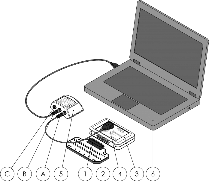
Preparing for a Clinical Feasibility Study with the Brain Interchange Evaluation Kit
To prepare for the study, we are using special equipment called the Brain Interchange Evaluation Kit. It allows researchers to test the system’s performance. Thus the Evaluation Kit plays a great role for the upcoming study by enabling the collection of in vivo data. Subscribe to the CorTec Newsletter to get further updates.
You can read the full article here.
Learn More about the Brain Interchange System and our Technology
- More information about Brain Interchange Technology: Brain Interchange One
- Explore our other breakthrough products: Products and Services
- Read these stories to discover our innovative solutions: CorTec Stories
- For more technical information of our Brain Interchange System and the Evaluation Kit please download our Product Catalogue