How to Implant °AirRay Tunnel Cuff Electrodes

°AirRay Cuff electrodes make contact with peripheral nerves. These can also be very finely structured, so that the electrodes interfacing them may only have a diameter of 100 µm. The implantation of the cuff represents a big challenge in these small dimensions.

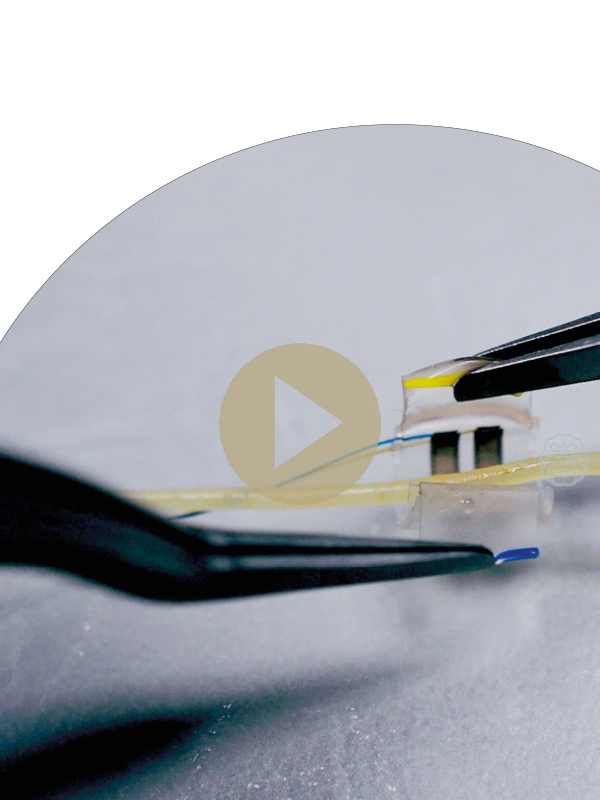
In a short video we have compiled a few tips around the implantation of Cuff electrodes – in this case especially for the °AirRay Tunnel Cuff. In order to demonstrate how cuff and nerve interact served ourselves in the kitchen and got the perfect nerve substitute – spaghettini al dente.

Our CTO and CEO Dr. Martin Schüttler demonstrates in the tutorial how the nerve is exposed, the cuff is prepared and finally implanted. The spaghettini imitate the characteristics of nerves in a perfect way: just like a nerve, they are very flexible, soft and easy to damage.

The video not only gives a comprehensive insight into the process of implantation, but also deals with the „Dos“ and „Don’ts“ around the handling of cuffs and nerves.

Watch the video

Click here to find different solutions for interfaces to the peripheral nervous system
Further readings in Technology and User Stories:
No data was found

Contact

Do you have any questions regarding our Company, our Products or our Technology?
We are happy to receive your message!

Get a Quote

We’re happy to help you realize your next project. Whether it is a complete implantable system design, an electrode or another component.

Please fill out the form below and our sales team will be in contact with you shortly.

SPECIFICATIONS

FEATURE 

Recording channels 

Sampling rate 

Sampling dynamic range 

High pass filter cut-off 

Low pass filter cut-off 

Amplifier band pass gain 

Band pass roll-off 

Reference


Stimulation 

Stimulation channels 

Current 

Current source 

Pulse width 

Power supply 

Wireless data transmission 

Closed Loop latency

VALUE

32 

1 kHz 

16 bit (74 nV smallest increment) 

ca. 2 Hz 

325 Hz 

Adjustable: 100-750 

20 dB/dec 

Any (subset) of the recording channels selectable by software or one dedicated hard-wired additional contact 

Current-controlled, biphasic, rectangular, asymmetric stimulus pulses (cathodic amplitude with pulse width followed by an anodic counter pulse of 1/4x amplitude and 4x pulse width) 

 32 

Max. -6 mA / +1.5 mA (24 µA increments) within

 compliance voltage range of -11 V to +5 V 

Can be directed to any of the 32 electrode contacts 

Negative phase: 10 µs – 2,500 µs

Wireless inductive, 120-140 kHz

Bi-directional, radio frequency in 2400-2483.5 MHz band ≤ 40 ms