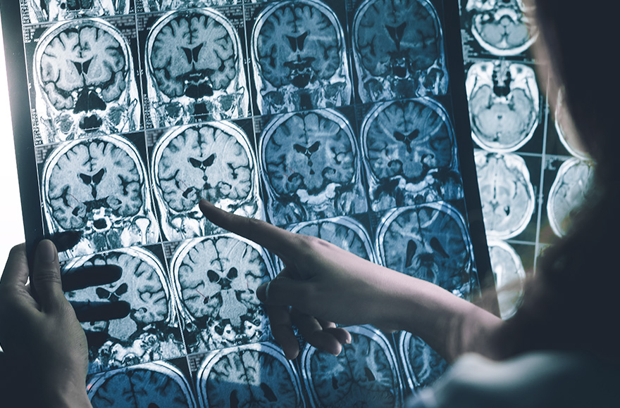
Presurgical Diagnostics
Some brain diseases may require surgical removal of the affected parts of the brain. Examples of such cases include pharmacologically resistant epilepsy and brain tumors.
In order to precisely locate the diseased brain tissue and to protect healthy areas that mediate important brain functions, the brain must be “mapped” before surgery. The aim of this mapping is to determine the location and extent of different brain areas and the abnormal tissue as precisely as possible.
Implanted depth electrodes as well as grid-like foil electrodes (also called grid and strip electrodes) are the most precise way to map the brain. Depth electrodes measure the brain activity in deeper brain regions. Grid and strip electrodes are located on the surface of the brain tissue and enable communication with the underlying local groups of nerve cells.
Because they are in direct contact with brain tissue both types of electrodes can detect the electrical signals of the brain with better resolution than external electrodes that are used in electroencephalogram (EEG) for example (Enatsu & Mikuni, 2016).
To ensure a reliable diagnosis, electrodes are implanted over a period of several days to weeks, during which they are used to record electrophysiological signals and sometimes also electrically stimulate. In some cases, e.g. in the process of removing brain tumors, the electrodes are usually used only during the surgery in which the diseased brain tissue is resected.
Grid and strip electrodes as well as depth electrodes have been successfully used to map the brain in pre-surgical diagnostics for several decades. Recent research indicates that electrodes with higher contact densities could yield even more accurate diagnostic results (Hermiz et al., 2018, Wang et al., 2017).
The grid and strip electrodes that are used in clinical practice to date are manufactured mostly by hand. The conventional production techniques render those electrodes in high contact densities very hard and stiff.
The °AirRay Cortical Electrode includes a set of grid and strip electrodes for presurgical diagnostics. They are manufactured in a patented laser-assisted process and their properties make them ideal for brain mapping:
- The electrodes are thin and soft, so that they can very well adapt to the curved surface of the brain.
- A special interlocking mechanism of the materials prevents a detachment of the contacts from the grid. The electrodes can thus provide an increased level of patient safety.
The °AirRay Cortical Electrode to be submitted to the FDA for approval for clinical use is in preparation. In individual cases, the electrode technologie has already been used successfully in patient-individual custom-made products for presurgical diagnostics.
The special production technology of CorTec allows in principle high contact densities without making the electrodes very hard and stiff. The current FDA submission of the °AirRay Cortical Electrode, however, does not include such designs yet.
General background literature
CorTec Press-Release March 2017
Little Girl Overcomes Big Disease – Thanks to Latest Technology
EEG
https://www.webmd.com/epilepsy/guide/electroencephalogram-eeg
Epilepsy Surgery
Scientific Literature
Invasive Evaluations for Epilepsy Surgery: A Review of the Literature.
Enatsu R, Mikuni N.
Neurol Med Chir (Tokyo). 2016 May 15;56(5):221-7. doi: 10.2176/nmc.ra.2015-0319. Epub 2016 Mar 4. Review.
Sub-millimeter ECoG pitch in human enables higher fidelity cognitive neural state estimation.
Hermiz J, Rogers N, Kaestner E, Ganji M, Cleary DR, Carter BS, Barba D, Dayeh SA, Halgren E, Gilja V.
Neuroimage. 2018 Aug 1;176:454-464. doi: 10.1016/j.neuroimage.2018.04.027. Epub 2018 Apr 18.
Wang X, Gkogkidis CA, Iljina O, Fiederer LDJ, Henle C, Mader I, Kaminsky J, Stieglitz T, Gierthmuehlen M, Ball T.
J Neural Eng. 2017 Oct;14(5):056004. doi: 10.1088/1741-2552/aa785e. Epub 2017 Jun 9.