When electrically stimulating a nerve to modulate a specific body function for treating a disease, it is essential to know exactly what you are doing. Peripheral nerves typically are heterogeneous bundles of fiber groups (fascicles) that can carry a variety of functionally different signals from or to different body parts. To evoke a specific response, one must precisely tweak the stimulation such that only the desired subset of fibers is stimulated. Electrical Impedance Tomography (EIT) is a powerful tool that helps researchers monitor the electrical activity within a nerve with high temporal resolution in the order of milliseconds.
Up until now, this technology was bulky and prohibitively expensive for many neuroscience labs. A group of engineers at the University College London, who have been pioneering the EIT technology, has now come up with a simplified hardware solution. It meets all requirements for bioelectronic medicine applications and, yet, is cost-efficient enough to be applied by any lab.
The setup makes use of as many inexpensive off-the-shelf components as possible. It combines them with standard electrophysiology equipment such as EEG amplifiers that are part of the basic equipment of many electrophysiology labs.
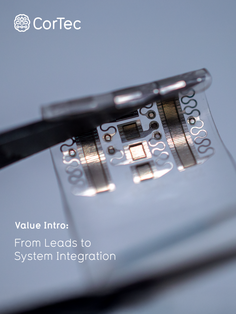
After bench testing, the group applied their new device in animal experiments, using the rat sciatic nerve as a model. CorTec’s °AirRay cuff electrodes were used to stimulate different nerve branches that activate different nerve fascicles. Simultaneously, the evoked responses were recorded by the new EIT device. The authors were able to produce cross-sectional images through the nerve that faithfully resolved the different fascicles that were being activated as response to the stimulation of different nerve branches.
The new technology proved to be comparable in image quality and signal-to-noise ratio to commercial EIT devices. The cost-efficiency of the new solution makes EIT a very promising tool for speeding up bioelectronic medicine research. To facilitate this process, the authors will now integrate their system into an embedded “Nerve EIT Board” that would be ready for a wide dissemination among neuroscience labs.
Citation:
Ravagli E, Mastitskaya S, Holder DS, Aristovich KY. Simplifying the hardware requirements for fast neural EIT of peripheral nerves. Physiol Meas. 2021 Dec 16. doi: 10.1088/1361-6579/ac43c0. Epub ahead of print. PMID: 34915462.
Get more insights about the use of our products in bioelectronic medicine.