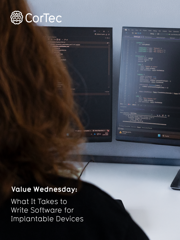
Active implantable devices have evolved beyond hardware with embedded software. They are now defined by software that extends across the implant, PC applications and services, and cloud infrastructure. Working in this space demands strict adherence to safety and regulatory requirements, within extreme technical constraints, while keeping a constant focus on therapy success. Addressing all three at once is what makes this field so specialized, and so dependent on exceptional individuals.
Safety and Security: A Highly Regulated Field
Implantable device software directly controls stimulation and recording in the human body. Errors here pose a risk to patient safety, which drives every decision, from architecture to code review to the release process. Safety-critical functions are checked independently at multiple layers, from the cloud to the firmware, so no single bug can compromise patient safety on its own.
Full traceability connects requirements, design, and test results across every layer. Regulatory rigor, such as IEC 62304, provides proof that the system behaves as intended. Risk analysis and verification requirements also limit reliance on third-party libraries, particularly close to the implant, meaning more of the stack is built and validated in-house.
Specialized Firmware and PC Software: Low Power Meets High Performance
Recording and stimulation must be performed at the highest technical level, within power budgets measured in microamps. This demands peak performance from the embedded hardware. The result is lean, hardware-near firmware where every cycle and every microjoule is optimized, a discipline closer to precision engineering than conventional application development.
Implantable devices focused on data acquisition require specialized wireless systems for both power and data transfer. Common protocols like Wi-Fi or Bluetooth either consume too much power or lack the required data throughput, which is why custom-built solutions are the standard.
Usability as a Safety Feature
Every technical decision ultimately serves one goal: does the therapy work, and does it reach the patient quickly? Speed of therapy matters. Architecture and processes should not hinder what actually helps people.
Clinicians and patients need to trust and understand the system from the first interaction. Intuitive PC, app, and cloud interfaces reduce the risk of user error, which is why usability and safety design are treated as one workstream, not two.
The People Behind Modern Implantable Device Software
Meeting these demands, safety-critical rigor, low-power engineering, and a focus on therapy outcomes, takes engineers who move fluidly between embedded programming, app development, and risk analysis, while staying close to clinicians and customers in the field. Few people combine deep technical depth across these domains with the judgment to see how it all serves the patient. That combination is built over time, which is why small, tightly knit teams can punch far above their size.
How CorTec Supports Your Software Development
CorTec offers software development services from proof-of-concept prototypes to fully IEC 62304-compliant software, with a strong focus on implantable medical devices, developed alongside the electronics rather than after them.
Close to the hardware, this includes safety-critical bootloader firmware with fallback protection, real-time stimulation control and sensor acquisition firmware on resource-constrained microcontrollers, and custom low-power, high-bandwidth radio protocols. CorTec also supports the surrounding processes: risk analysis, requirements engineering, and hardware-independent unit test frameworks.
Beyond the device itself, CorTec builds the software that connects it to patients and clinicians: apps for tablets and smartphones to control your therapy system, paired with CorTec Cloud, secure and customizable cloud services for transferring and analyzing neural recordings and time series data, accessible via Android, Windows, and Apple client apps.
Parts of the Brain Interchange system, already running in an FDA-cleared study, can be integrated into your own active implantable medical device, giving your project a faster path to market.
From a single proof-of-concept firmware module to a fully IEC 62304-compliant software stack, CorTec accompanies your project from first prototype to market. If you are developing an implantable device and want to discuss your software requirements, get in touch.